Why Gate Design Makes or Breaks Your Injection Mold
If you’ve ever struggled with short shots, weld lines, or sink marks in your injection molding process, chances are the root cause lies in gate design. The gate is the “entry point” where molten plastic enters the cavity — and a poor choice here can cascade into quality issues, wasted material, and endless trial-and-error tweaking.Whether you’re building a custom injection mold for a new product or optimizing an existing injection mold for high-volume production, mastering gate design is non-negotiable. Today, I’ll share 5 golden rules drawn from decades of shop-floor experience — so you can stop guessing and start getting consistent, high-quality parts from your injection molding runs.
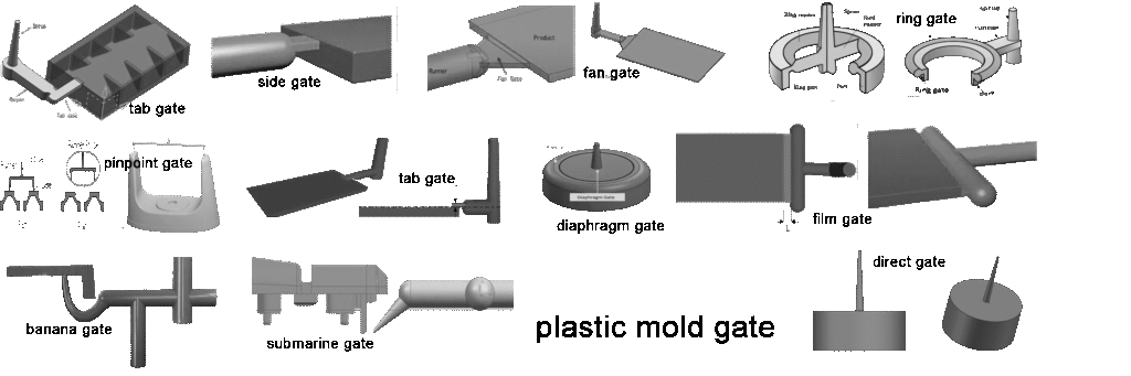
Rule 1 – Match Gate Type to Part Geometry & Material
Not all gates are created equal. Selecting the wrong type for your part’s thickness, shape, and material leads to filling imbalances and defects.
| Gate Type | Best For | Pros | Cons |
|---|---|---|---|
| Edge Gate | Flat parts, simple geometry | Easy to machine, low cost | Leaves visible mark, limited placement flexibility |
| Submarine Gate | Automotive/electronics where gate vestige must be hidden | Hidden gate scar, automated degating | Complex machining, higher mold cost |
| Pinpoint Gate | Small or delicate parts | Minimal gate vestige, precise location | Prone to freezing off in large parts |
| Fan Gate | Wide flat surfaces | Reduces flow hesitation, improves surface finish | Larger gate scar |
| Hot Runner Gate | High-volume custom injection molds | No runner waste, shorter cycle time, precise control | High initial cost, requires maintenance |
Pro Tip: For glass-filled materials (e.g., PA66+GF), avoid pinpoint gates — the small cross-section accelerates wear and can freeze prematurely.
Rule 2 – Position Gates Where Filling Is Most Uniform
Gate location dictates how plastic flows through the cavity. Misplaced gates create flow hesitation, leading to short shots in thin sections and overpacking in thick sections.
- Place gates opposite the thickest section — this allows the melt to push forward evenly, reducing sink marks.
- Avoid placing gates near moving cores/sliders — interference risk and difficult degating.
- For symmetrical parts, center the gate or use multiple gates to balance flow fronts.
- For irregular shapes, simulate flow with CAD software (e.g., SolidWorks Plastics, Autodesk Moldflow) to visualize flow length differences.
Case Example: A client’s custom injection mold for a rectangular battery cover used a single edge gate near one corner. Result: the far corner consistently shorted. Moving the gate to the center and adding a small secondary gate eliminated the issue.
Rule 3 – Balance Flow in Multi-Cavity Molds
In multi-cavity molds, uneven runner lengths or diameters cause some cavities to fill faster than others — producing inconsistent parts and wasting material.
- Use symmetrical runner layouts so each cavity has the same distance and resistance from the sprue.
- Calculate runner diameter using flow balance equations:D=√4Q/πv
where Q= volumetric flow rate, v= recommended melt velocity (typically 100–300 mm/s for thermoplastics).
- Match gate sizes across cavities — even a 0.2 mm difference can create imbalance.
Pro Tip: For high-cavitation molds (16+ cavities), consider hot runner systems to maintain melt temperature and reduce balancing complexity.
Rule 4 – Control Gate Size to Manage Shear & Freeze-Off
Gate cross-sectional area determines shear rate (which affects material degradation) and freeze-off time (which controls packing pressure).
- Shear-sensitive materials (e.g., PVC, PC) → larger gates to reduce shear heating.
- Fast-cycle applications → smaller gates to freeze earlier, allowing faster mold open/close.
- Typical gate widths: 1–3 mm for small parts; 3–8 mm for larger parts.
- Typical gate thickness: 0.5–1.5 mm for thin walls; up to 2× wall thickness for thick sections.
Caution: Excessively small gates increase injection pressure, accelerating wear on the injection mold and risking gate freeze before packing completes.
Rule 5 – Choose Cold Runner vs. Hot Runner Based on Economics & Quality Goals
- Cold Runner: Simple, low upfront cost, but generates plastic waste (runners must be trimmed and recycled). Best for low-to-medium volumes or prototyping.
- Hot Runner: Eliminates runner scrap, reduces cycle time, and improves consistency — ideal for high-volume custom injection molding. Requires precise temperature control and periodic maintenance.
Decision Factors:
1.Annual volume – Hot runners pay off above ~50,000 shots.
2.Material cost – High-value resins justify hot runner investment.
3.Part appearance – Hot runners enable hidden or pinpoint gates for premium finishes.
Putting It All Together – A Gate Design Checklist
✅ Selected gate type matches part geometry & material.
✅ Gate positioned for uniform filling, away from moving parts.
✅ Multi-cavity runners balanced for equal flow resistance.
✅ Gate size tuned to material shear sensitivity & cycle goals.
✅ Chosen cold vs. hot runner based on volume & economics.
Following these 5 golden rules will drastically improve your injection molding success rate — especially critical for custom injection mold projects where rework is costly and time-consuming.
Final Thought
Gate design isn’t just a “detail” — it’s the foundation of reliable injection molding. Get it right, and your injection mold will deliver consistent quality, faster cycles, and fewer headaches. Get it wrong, and even the best mold can feel like a money pit.Need help optimizing gate design for your next custom injection mold? Share your part drawings and material specs, and our engineers will give you a free DFM review.(P.S. Want a printable gate design checklist? Comment “GATE CHECKLIST” and we’ll email it to you.)